ArcGIS, an integrated server-based GIS is hosted and managed by Esri to share geographic information throughout an organization, community and openly on the web. It aids in analyzing and visualizing the compiled geographic data by leveraging its integrated tools to facilitate mapping and spatial reasoning.
This instructional tutorial aims at illustrating a specific use-case for employing ArcGIS connector within an interaction flow to compute a geometric intersection in order to retrieve location-based information. Adopting a comprehensive methodology, the tutorial is broken down into multiple sections of configuring an ArcGIS connector instance by making use of the Spatial Relationship ‘Intersects’ together with implementing it in an interaction flow. This enables accessing desired data from a selected feature layer based on calculating the areas where the input geometry intersects with an ArcGIS polygon layer.
Prerequisites
- VOGO Voice account: https://www.vogovoice.com/
- Access rights to the Interactions section.
- Access rights to the Interaction builder platform.
- Base URL of the desired geodatabase.
- Alexa device (In the case of sending device location information as geometry input choose an appropriate device such as Alexa Auto, Alexa Echo Buds or Alexa app on the phone)
Setting up an ArcGIS connector instance
In order to create an ArcGIS connector instance
- Log into your VOGO Voice account to be directed to VOGO Voice Management Console (https://account.vogovoice.com)
- Navigate to Settings on the top right-hand corner of the Dashboard and select Integration from the list of tabs displayed.
Settings > Integration - Click on the Add Button on the top left-hand corner of the screen to create a new connection.

4. In the Select Account Type window, choose the ArcGIS icon from the list of connectors and click Create Connector button which opens up Add New ArcGIS Account window.
5. Populate the required fields in the Add ArcGIS Connector window.
Field values
Base URL: Source the Base URL of the desired geodatabase that consists of the URL endpoint up to ‘/arcgis/rest’. It allows the instance of the connector to access all the corresponding feature servers hosted by the ArcGIS REST Service for a specific database. Here, the Base URL is https://services.arcgis.com/P3ePLMYs2RVChkJx
To learn how to locate the URL of the geodatabase refer the ArcGIS connector guide: https://university.vogovoice.com/kb/arcgis/
6. After filling in the required fields click the Save button to set up and integrate the connector instance with the platform.
Steps to Configure the ArcGIS connector
Once the ArcGIS connector has been created, navigate to Interactions and click on the Interaction button at the bottom right-hand corner of the screen. Select the required intent to be directed into the Interaction builder platform.
Now let’s create an interaction flow to introduce the user to an ArcGIS example where the input geometrical point intersects the ArcGIS polygon layer while implementing the Spatial Relationship ‘Intersects’ thereby enabling the user to utilize the feature layer to compute basic intersection.
- In the flow diagram area, you will be able to see the Start and Response component.
- Roll the mouse over the Response component to see the voice, computer and camera icon on the top right-hand side of the component.
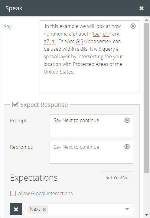
- Clicking on the Voice icon opens a Speak pop-up window with a field titled Say wherein you need to type the voice action intended to be spoken to the user in regard to introducing the relevance of ArcGIS connector through an example of a basic intersection.
Say: In this example we will look at how <phoneme alphabet=”ipa” ph=’ark dZi.aI.”Es’>Arc GIS</phoneme> can be used within skills. It will query a spatial layer by intersecting your location with Protected Areas of the United States.
🖍 Note: The phoneme focused syntax <phoneme alphabet=”ipa” ph=’ark dZi.aI.”Es’>Arc GIS</phoneme> is provided for the voice action to accurately relay the pronunciation of ‘ArcGIS’ - Check the checkmark box in the Expect Response and type in the suitable Prompt message to proceed with the flow.
Prompt: Say Next to continue.
The same message will be replicated in the Reprompt field. - Populate the field under Expectations by selecting the Global Intent Next from the drop-down list.
6. Drag and drop the ArcGIS component onto the flow diagram area and connect the anchor symbol of Next on the Response
card to the ArcGIS component.
🖍 Note: To interconnect the different components click on their respective Anchor symbols so as to chain and hold them in the interaction flow.
7. Double click the ArcGIS component, or click the pencil to access the Configuration window and fill in the required fields to capture the input geospatial location, compute the geometric intersection and to retrieve the desired data from the selected Feature Layer.
Setting up the configuration fields
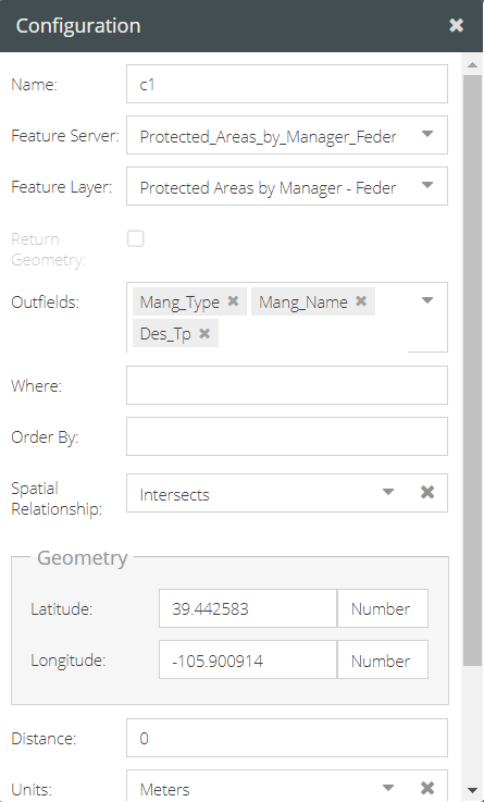
Name: The name is provided by default and can be changed manually. It is used to identify the connector instance and how it is referenced throughout the flow.
Feature Server: Click the drop-down list and select the desired feature server. Here, the feature server pertains to America’s official national inventory to retrieve USGS protected areas data.
Protected_Areas_by_Manager_Federal
Feature Layer: A feature server may contain multiple feature layers. Clicking the drop-down list allows you to select the desired feature layer from which the relevant geospatial data has to be retrieved. In this case, the selected feature server has only one feature layer which is Protected Areas by Manager – Federal (0)
Outfields: Selecting the required feature layer will automatically populate the drop-down list of Outfields. From the list choose the fields or attributes to be included in the returned resultset. Here, the selected outfields are Mang_Type, Mang_Name, Des_Tp.
Spatial Relationship: In order to calculate the geometric intersection of the input point value against the ArcGIS polygon layer, set the Spatial relationship to Intersects by selecting it from the drop-down list.
Geometry: Selecting any type of Spatial Relationship will generate an additional section in the Configuration window titled Geometry to capture the input geolocation values. The latitudinal and longitudinal points can either be hardcoded values or defined using the syntax geolocation.latitude and geolocation.longitude to capture the location of the device.
As shown in the screenshot below, type in the point values and set its data type to Number. Set the Distance to ‘0’ as we want to retrieve data by calculating the exact point where the input value intersects with the polygon layer. Unit of distance can be selected from the drop-down list based on the requirement.
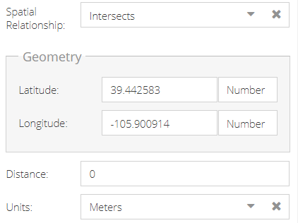
👍 Note: Distance refers to the buffer distance of the input geolocation value to decide the buffer zone based on which the Spatial Relationship computation has to be done. The size of a buffer zone varies depending on the numerical value in the Distance field.
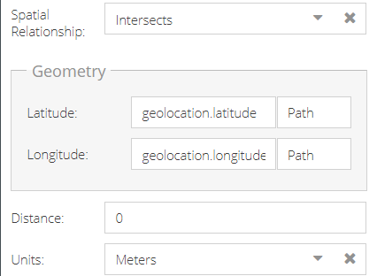
The screenshot below demonstrates how the Geometry fields need to be populated for the device location to be captured. Here, ensure that the data type is chosen as Path.
To learn about the additional parameters in the Configuration window visit: https://university.vogovoice.com/kb/arcgis/
8. Drag and drop another Response component onto the flow canvas. You can alternatively right click on the anchor icon and choose the response component.
9. Connect the ArcGIS component to the Response card by click both anchors.
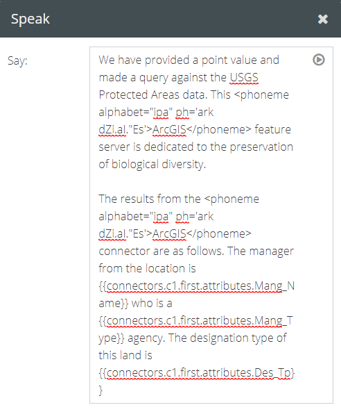
10. Click on the Voice icon of the Response card to open up the Speak pop-up window as mentioned before and type the voice action intended to be spoken to the user in regard to the data retrieved from the attribute table.
Say: We have provided a point value and made a query against the USGS Protected Areas data. This <phoneme alphabet=”ipa” ph=’ark dZi.aI.”Es’>ArcGIS</phoneme> feature server is dedicated to the preservation of biological diversity.
The results from the <phoneme alphabet=”ipa” ph=’ark dZi.aI.”Es’>ArcGIS</phoneme> connector are as follows. The manager from the location is {{connectors.c1.first.attributes.Mang_Name}} who is a {{connectors.c1.first.attributes.Mang_Type}} agency. The designation type of this land is {{connectors.c1.first.attributes.Des_Tp}}
To learn about different template engines to be followed to run functions visit https://university.vogovoice.com/kb/template-engine/
To add a display message in a video-enabled voice-assisted device
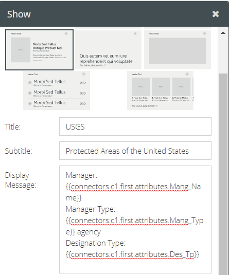
- Click on the Computer icon, and type in a condensed version of the voice message in the field titled Display Message of the Show pop-up window.
- Populate the required fields and click the Save button.
Title: USGS
Subtitle: Protected Areas of the United States
Display Message: Manager: {{connectors.c1.first.attributes.Mang_Name}}
Manager Type: {{connectors.c1.first.attributes.Mang_Type}} agency
Designation Type: {{connectors.c1.first.attributes.Des_Tp}}
For further reference on how to populate the additional fields visit https://university.vogovoice.com/kb/guide-response-component/
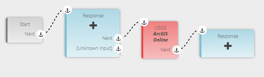
The screenshot below captures the aforementioned interaction flow
Testing and Validation
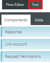
- Click on the Test button next to the Flow Editor button on the interaction builder platform.
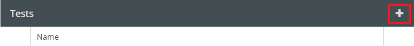
2. In the Tests pop-up window that appears click the + button on its top right-hand corner.
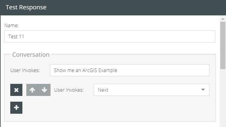
3. Fill the Name field of the Test Response window that shows up, then populate the field titled User invokes by selecting the Next intent called to action within the interaction flow.
Optional step: In the case of calculating intersects by accessing the device location, check the checkmark box of Geolocation under User Permissions to represent the permission granted by the user to capture the location of the device. Provide the latitudinal and longitudinal values accordingly to run the test. This is applicable only if the geometry input is not hard-coded values but of the syntax geolocation.latitude and geolocation.longitude.
4. Finally, click the Save button to save the input and perform the test.
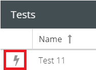
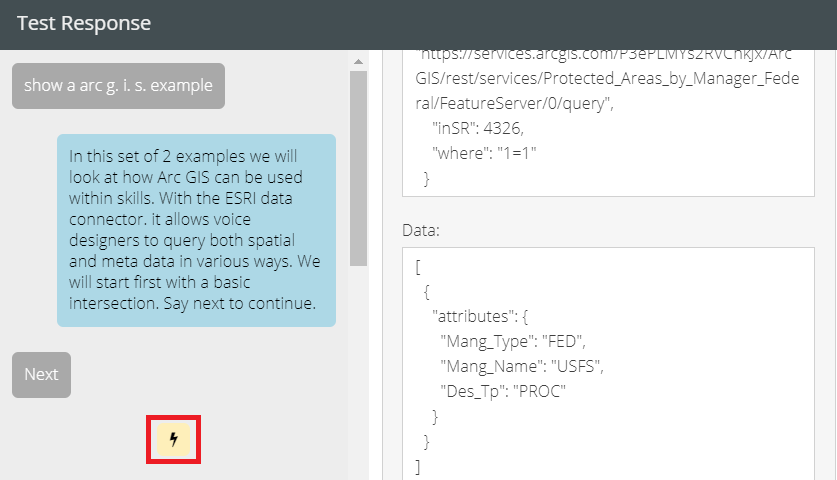
5. To validate the Test Response, click on the lightning symbol on the left-hand side of the test case.
6. On the resultant Test Response window, the blue chat bubbles will cumulatively present the previously input message within the Response components. The lightning bolt symbol in yellow represents the ArcGIS connector.
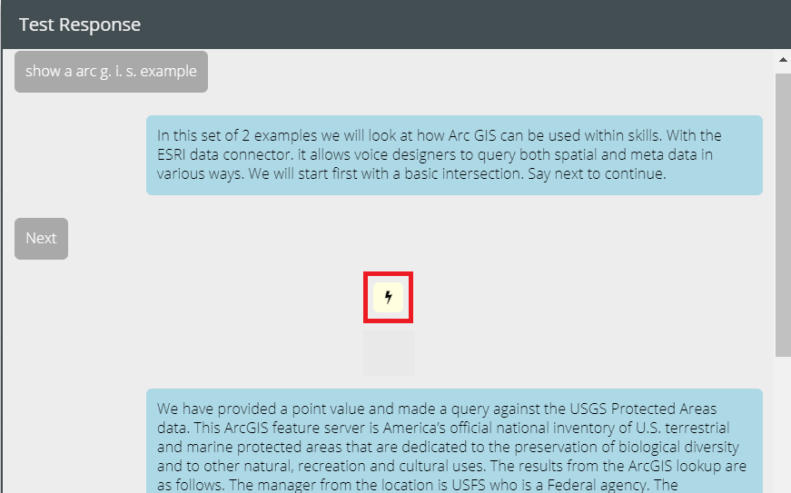
7. Click on the chat bubble to see the details of the individual responses. To take a detailed look at the data fetching part of the connector instance, click on the lightning bolt icon highlighted in yellow.
To know more about testing an interaction refer https://university.vogovoice.com/kb/testings/
Congratulations! You have successfully created an interaction using an ArcGIS connector instance that intersects a polygon layer based on a provided point.
👍 Note: To test the functioning of the interactions on your device you have to deploy the custom skill to facilitate it with the new edits. To accomplish this, click on the Deploy button seen at the bottom of the Skill Settings pop-up window.
To know how to deploy a custom skill visit https://university.vogovoice.com/kb/deploying-a-skill/
- To learn about ArcGIS connector, click here.
- To access the tutorial on ‘ArcGIS: Intersects buffer of a provided point’, click here.